1900/65A 1900/65A-01-01-01-00-00
Description
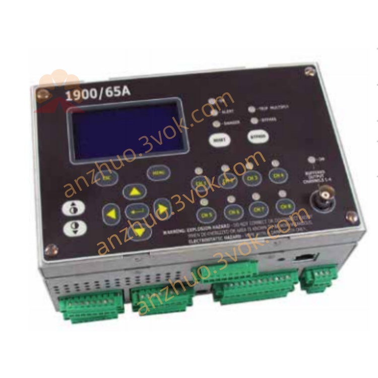
1900/65A (Model: 1900/65A-01-01-01-00-00)
Brand: Bently Nevada (Bently Nevada)
Product Full Name: General Purpose Equipment Monitor
Position: Low-cost, multi-channel independent monitor, used for continuous protection of vibration, displacement, temperature, and speed of non-critical rotating machinery/equipment, replacing the economical solution of the traditional 3500 series.
I. Model Code Analysis (1900/65A-01-01-01-00-00) Table
Section Code Explanation
1 01 Power supply: 110–220 VAC, 50/60 Hz
2 01 Display: Built-in display (no cable)
3 01 Installation: Panel-mounted
4 00 Approval: None
5 00 Communication: No Modbus
II. Core Parameters
1. Input channels (8 channels)
Vibration / Displacement / Speed × 4: Support 2/3-wire accelerometers, speed sensors, eddy current probes (shaft vibration / axial displacement)
Temperature × 4: Support E/J/K/T thermocouples, 2/3-wire RTD (PT100)
Sampling accuracy: 24-bit ADC, high resolution
2. Output
Relay × 6: Programmable (single channel / combinational logic), contact capacity: 250 VAC / 3 A (resistive), 250 VAC / 1.5 A (inductive)
4–20 mA × 4: Arbitrary channel variable transducer output, connected to DCS/PLC
Buffer output × 4: Buffer for raw sensor signals, for oscilloscope / portable meter verification
3. Electrical
Power supply: 110–220 VAC, 50/60 Hz (Model 01)
Power consumption: ≤ 25 W
Insulation: Input / Output isolated from power supply ≥ 500 VAC
4. Environment and Mechanics
Operating temperature: 0 ~ +60 °C
Storage temperature: -40 ~ +85 °C
Humidity: 5%–95% (no condensation)
Size (width × height × depth): 152 × 100 × 50 mm (panel-mounted)
Weight: Approximately 0.77 kg (main unit) + 0.4 kg (display)
III. Main Functions
Multi-parameter monitoring: Simultaneously monitor 4 channels of vibration / displacement / speed + 4 channels of temperature, covering key indicators of general equipment.
Independent alarm / danger: Each channel has independent alarm (Alert) and danger (Danger) thresholds, supports voting logic (AND/OR), 6 relays freely mapped.
Event recording: 200 historical events (timestamp, channel, status), facilitating fault traceability.
Configuration flexibility:
Software: 1900 Configuration Software (PC), Ethernet download configuration.
Local: Built-in display for viewing real-time values, status, supports simple parameter modification.
Bypass / Reset: Supports external contacts to disable alarm (Inhibit), reset alarm (Reset), threshold multiplication (Trip Multiply), suitable for startup / maintenance scenarios.
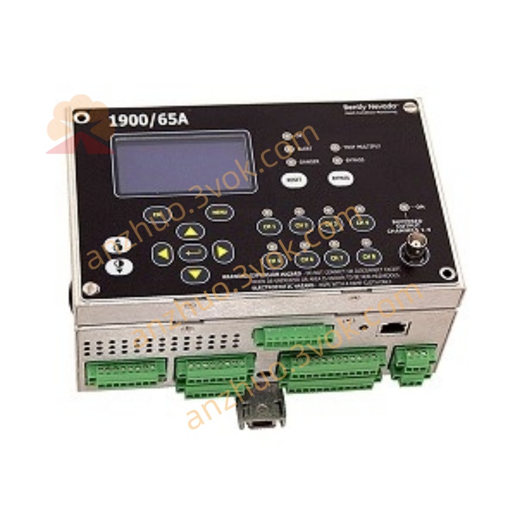
IV. Panel and Wiring
1. Front panel
LCD display: Real-time values, channel status, alarm / danger indication
Buttons: Menu/Enter/↑/↓, local operation
LED: PWR (power), RUN (operation), FLT (fault), CH1–CH8 (channel status)
2. Back panel wiring (terminal block)
Power: L/N/PE (110–220 VAC)
Sensor input: CH1–CH4 (vibration / displacement), CH5–CH8 (temperature)
Relay output: RL1–RL6 (each channel COM/NO/NC)
4–20 mA output: AO1–AO4 (+/-)
Control input: Inhibit/Reset/Trip Multiply (contacts)
Ethernet: RJ45, for configuration software connection
V. Installation and Configuration
Installation: Standard panel mounting holes (152×100 mm), fix the main unit; display and main unit integrated (Model 01).
Wiring:
Sensor: Shielded wire is grounded at one end, avoiding strong interference from the frequency converter / motor.
Relay: Strong current circuit is connected with a 3 A fuse, with NO/NC options for connecting the alarm light / stop circuit.
Configuration steps:
Connect the device to the Ethernet, and open the 1900 configuration software.
Define the channel type (vibration / temperature), range, alarm / danger threshold.
Configure the relay mapping (e.g. CH1 danger → RL1 action).
Download the configuration, and restart after power off to take effect.
Six. Common Faults
FLT red and bright: Power abnormality, configuration error, sensor short circuit / open circuit → Check power supply, re-download configuration, verify wiring.
No display of channels: Sensor failure, wiring break, range error → Replace sensor, check wiring, verify configuration.
Relay does not act: Mapping error, threshold not triggered, contact damage → Check configuration, confirm over-limit, measure contacts.
Get a Quote