9100-00001-06
Description
Model Description
9100-00001-06
9100: EPRO Passive Magnetic Resonance Speed Measurement / Phase Alignment Sensor Series
00001: Standard Body Specification
06: Cable Length 6 Meters
Core Parameters
Working Principle: Passive Magnetic Induction Type, No Power Supply Required
Applicable Objects: Gear Teeth, Phase Alignment Grooves, Ferromagnetic Protuberances
Applicable Speed Range: 0 - 30000 rpm
Frequency Response: 0 - 10 kHz
Recommended Installation Gap: 0.5 - 1.5 mm, Optimal 1.0 mm
DC Resistance of Coil: 200 - 250 Ω (Normal Temperature)
Output: Inductive Sine Pulse Voltage, Changes with Speed and Gap
Probe Installation Thread: M16×1
Cable: 6 Meters Double-Layer Shielded Oil-Resistant Cable
Operating Temperature: -20℃ - +85℃
Protection Grade: IP67
Applicable Teeth Disk: Module m ≥ 2 Ferromagnetic Material Teeth Disk
Connection method
Two-wire passive output:
Signal line 1, Signal line 2
Shielding layer: Only single-point grounding on the control cabinet side, the probe end is left floating
Installation and commissioning key points
The probe should be vertically aligned with the top of the speed measuring gear disk, centered and aligned
The installation gap should be controlled within 0.8 - 1.2mm for the best result
The cable should be kept away from the power cable and the frequency converter to avoid parallel and co-located laying
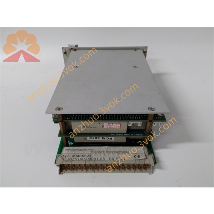
Compatible accessory modules: MMS6120, MMS6312, etc. for speed / phase matching modules Application scenario
Steam turbines, compressors, fans, gas turbines
Used for speed measurement, zero-speed monitoring, and phase angle acquisition
Get a Quote