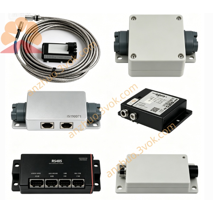
PR6423/003-030+CON021
Description
I. Model Interpretation PR6423/003-030
PR6423: Φ8mm Eddy Current Sensor Series
003: Armored Cable - 5 meters
030: Standard Sensitivity, Standard Linear Calibration Version
CON021: EPRO Specialized Companion Pre-Amplifier, Compatible with the Entire Series of PR6423 Probes
II. Core Parameters of PR6423/003-030 Probe
Probe Diameter: 8mm
Installation Method: Threaded Fixed Type
Cable Specification: 5m double-layer shielded armored cable, with anti-tensile and anti-interference properties
Linear Measurement Range: 0 - 1.5mm
Sensitivity: 12V/mm
Standard Installation Gap: 2.5mm
Frequency Response: 0 - 12kHz
DC Resistance of Coil: 4 - 6Ω
Insulation Resistance: > 100MΩ
Operating Temperature: Probe -35℃ - +150℃, Cable -30℃ - +100℃
Compatible Materials: 42CrMo4 ferromagnetic steel, surface roughness Ra ≤ 3.2μm
III. Parameters of CON021 Preamplifier
Power Supply: -24VDC (allowable range -18 - -30VDC)
Static Output Voltage Range: -4V - -20V
Standard Working Point: When gap is 2.5mm, output is -12V
Overall Power Consumption: ≤ 2W
Frequency Response: 0 - 10kHz
Built-in Protection: Reverse connection, short circuit, open circuit protection
Installation Location: Installed in control cabinet, protection grade IP20
IV. Wiring Method
CON021 Terminal Definitions
Terminal 1: -24V power negative pole
Terminal 2: 0V power ground
Terminal 3: Signal Output (connected to TSI module MMS6110/MMS6312)
Terminal 4: Signal Common Ground
Connection between Probe and Preamplifier
PR6423 comes with LEMO aviation plug, which can be directly inserted into the CON021 interface and tightened for locking.
Shield Grounding Requirements
Only single-point grounding is required on the front-end cabinet side. The shielding layer of the probe end is suspended, and grounding at both ends is prohibited.
V. On-site Installation and Debugging Standards
Probe should be vertically aligned with the measured shaft surface, avoiding the edge of the shaft.
Initial Installation Gap Set at 2.5mm
After powering on, measure the output voltage of CON021 with a multimeter, adjust the probe position to stabilize at -12V, and then lock it.
Cable should be kept away from power lines and frequency converters, and the parallel walking distance should be ≥ 300mm. Different cable trays should be used for laying.
VI. Voltage Status Judgment (with -24VDC power supply)
Insufficient Gap: Output approaches -4V
Standard Working Point: 2.5mm corresponds to -12V
Excessive Gap: Output approaches -20V
No Voltage or Close to 0V: Probe disconnected, LEMO connector loose, power reversed
VII. Application Compatibility
Compatible Equipment: Steam turbines, compressors, fans, gas turbines
Measurement Applications: Shaft vibration, shaft displacement, eccentricity, phase monitoring
Compatible Systems: EPRO MMS6000 series, AMS6500 TSI system
Get a Quote