A6824
Description
EPRO A6824 Communication Interface Module (User Manual - No Diagram Version) I. Product Overview
A6824 is a Modbus communication interface module of the AMS6500 system from the EPRO brand under Emerson. It belongs to the core communication components of the A6000/AMS6500 TSI system, and is used for data interaction between the rotating machinery monitoring system (such as MMS6000/AMS6500) and the upper-level DCS/PLC. It supports both Modbus TCP/IP and RTU protocols, is hot-swappable, and complies with the API 670 standard.
II. Model Meaning
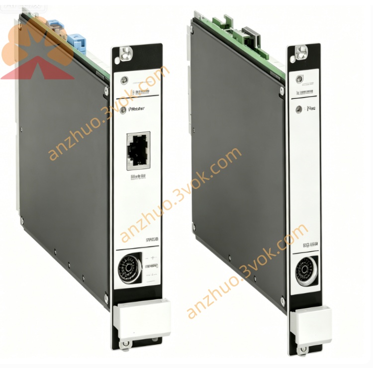
A6824: Standard type (6TE wide, without redundancy, IMR6000 rack)
A6824R: Redundant type (4TE wide, supports redundancy, IMR6500 rack)
III. Core Functions
Data Acquisition: Read real-time parameters and alarm status of AMS6500 series modules (vibration, speed, displacement, temperature).
Protocol Conversion: Support Modbus TCP/IP (Ethernet) and Modbus RTU (RS485) dual interfaces, suitable for different upper computer communication requirements.
Bus Expansion: Built-in 6 RS485 buses, each line can connect up to 8 A6000 series displays to achieve local data display and operation.
System Monitoring: Comes with hardware self-check, real-time monitoring of power, temperature, and communication status, automatic fault alarm and log recording.
IV. Technical Parameters
Electrical Specifications
Power Supply: 24VDC ±10%, working current 250mA, power consumption ≤6W.
Ethernet: 10/100Mbps auto-sensing, TCP/IP protocol, supports Modbus TCP master/slave mode.
Serial Port: 6×RS485, baud rate 1200~115200bps, supports Modbus RTU.
Insulation: Isolation voltage between power supply and communication interface ≥500VDC.
Physical and Environmental
Height: 3U (19" rack), 6TE wide (A6824) / 4TE wide (A6824R).
Operating Temperature: 0℃~+55℃; Storage Temperature: -40℃~+85℃.
Humidity: 5%~95% RH (no condensation); Protection Grade: IP20.
Weight: Approximately 0.3kg; Installation: DIN rail / 19" rack slot.
V. Wiring Definitions (Backplane Terminals) Power supply
+24V: Positive pole of DC 24V
GND: Power ground (shared with system ground)
Ethernet (RJ45)
1/2: TX+/- (transmitting)
3/6: RX+/- (receiving)
4/5/7/8: Empty
RS485 bus (6 channels, terminal block)
Each channel: A (+), B (-), GND (ground)
Terminal resistor: Set via jumper (both ends of the bus need to be connected)
Six. Configuration setup (AMS6500 software) Basic settings
Module Address: 1 - 247 (Modbus slave station address)
Ethernet IP: Static / Dynamic (DHCP), Subnet Mask, Gateway
Serial Port Parameters: Baud Rate, Data Bits (8), Stop Bits (1), Parity (None / Odd / Even)
Data Mapping
Select the monitoring parameters to be uploaded (vibration peak-to-peak value, rotational speed, displacement value, etc.)
Configure Modbus Register Address (Input Register / Hold Register)
Alarm Configuration
Enable / Disable module fault alarms (communication interruption, power anomaly, over-temperature)
Set alarm output contacts (Relay Dry Contact)
VII. Installation and Commissioning Installation
Rack: Insert into the vacant slots of the IMR6000/IMR6500 series 19" rack, and tighten the fixing screws.
Wiring: Ethernet cables should be kept away from power cables (≥ 300mm), and the RS485 bus should use double shielded cables with single-point grounding.
Power-on self-check
Normal: The green LED is constantly on; Fault: The red LED flashes (corresponding to power / communication / temperature abnormalities). Communication test
Modbus TCP: Verify by pinging the module IP through the upper computer (such as DCS) and reading the register data.
Modbus RTU: Send instructions using the serial port debugging tool to check if data transmission is normal.
VIII. Fault Troubleshooting
Ethernet communication failure
Check if the RJ45 connector is securely plugged in and if the network cable is damaged
Verify if the IP address, subnet mask, and gateway are on the same network segment as the upper computer
Disable the firewall / antivirus software, and test network connectivity
RS485 bus no data
Check if the A/B lines are connected in reverse and if the terminal resistor is correctly connected
Reduce the baud rate to eliminate interference; check the number of devices mounted on the bus (≤ 8 units / path)
Frequent module alarms
Measure if the power supply voltage is stable (24VDC ±10%)
Check if the rack ventilation is good and if the environmental temperature exceeds the limit (>55℃)
IX. Accessories and Selection
System Accessories: AMS6500 rack + A6824 + MMS6110 (vibration) + MMS6312 (rotation speed)
Redundancy Scheme: A6824R (redundant type) + dual power supplies, enhancing system reliability
Supplements: RS485 double-shielded cable, RJ45 industrial Ethernet connector, terminal resistor jumper wire
Get a Quote